Introduction to Lost Foam Casting for Complex Components
The lost foam casting process stands as a major step forward in foundry technology. This method works especially well for complex and large-scale components. The basic idea involves a sacrificial foam pattern that molten metal replaces. This approach gives great design freedom. It removes the need for traditional cores and complicated mold setups. For large hollow box-type castings such as machine tool beds, gearboxes, or structural frames, the process makes production steps simpler. It cuts pattern-making costs for one-off or low-volume runs. It also shortens the overall manufacturing cycle. Yet the application of lost foam casting to these difficult shapes brings certain challenges. These issues can influence yield and quality. Common defects include mold collapse, mold wall movement or swelling, and misruns. Real success needs a careful engineering method. This method must deal with the special physics at work.
Core Challenges in Hollow Cavity Castings
The main challenge comes from the large hollow cavity. In the lost foam casting process, the foam pattern turns into gas when it meets molten metal. These gases need quick removal through the coating and the dry sand around it. The sand receives compaction from applied vacuum. In solid castings, vacuum works evenly across the mold. In hollow castings, however, the internal cavity gets only indirect and often weak vacuum. This situation creates a key pressure difference. The external sand becomes tightly packed under full vacuum. The internal sand experiences lower effective vacuum. As a result, the internal sand shows reduced strength and problems with permeability. These conditions combine with dynamic pressures from metal filling and foam breakdown. They prepare the ground for problems to occur.
The basic mechanics focus on the forces that act on the internal sand mass. For the sand to stay stable, the net force must stay at zero or point downward. The main upward force is buoyancy from the molten metal. Forces that resist it include sand shear strength at contact areas and the weight of the sand mass. Shear strength relies strongly on effective internal vacuum and compaction. Weak internal vacuum lowers shear strength a great deal. Foam pyrolysis pressure and metallostatic pressure add forces that create instability. Stability demands that resisting forces stay greater than the upward disruptive forces. This requirement highlights the need to increase sand strength as much as possible and to decrease disruptive pressures.
Critical Defects and Their Root Causes
A clear understanding of defects remains essential for effective mitigation. Primary defects in large hollow castings produced by lost foam casting include the following.
Mold Collapse
This defect involves partial or complete breakdown of the mold cavity. It leads to a casting with wrong shape. The root cause lies in a strong pressure differential. This differential pushes the weaker internal sand outward. Insufficient gas evacuation also creates back-pressure. The back-pressure fluidizes the sand. The main factor is an excessive difference between external and internal vacuum. Gas pressure then exceeds sand cohesion.
Mold Wall Movement or Swelling
This problem causes dimensional inaccuracy, thicker sections, or changes in geometry. It comes from excessive buoyancy and gas pressure. These forces shift internal sand or bend mold walls. The shift often happens because of inadequate weighting or restraint. The imbalance appears when buoyancy and gas forces grow larger than sand shear strength, sand weight, and external restraints.
Misrun or Cold Shut
This defect means incomplete filling. It leaves unfused sections, especially in thin or distant areas. Causes include heat loss during the foam’s endothermic decomposition. Other factors are inadequate pouring temperature or rate and gas back-pressure that slows the metal front. The defect takes place when metal heat input cannot overcome foam vaporization and related losses.
Carbon Defects
These appear as shiny carbon films or pockets on the surface. They result from incomplete removal of pyrolysis gases. The gases crack into carbon residues that deposit on the metal front. Problems become worse with low permeability in hollow sections, insufficient vacuum, high gas pressure, and lower sand permeability.
Engineered Solutions for Robust Production
Solutions for these challenges require a strategy with many parts. The strategy centers on pattern integrity, gating, vacuum management, and mechanical stabilization.
Pattern Construction and Reinforcement
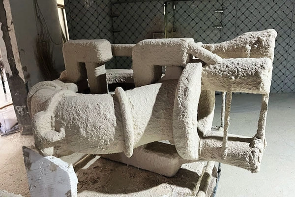
Large thin-walled hollow patterns made from foam boards do not have enough rigidity. They deform easily under weight, coating, or sand vibration. An integrated internal skeleton often made of lightweight metal or reinforced plastic becomes essential. It keeps dimensional stability from assembly through pouring. The skeleton withstands compaction forces. It keeps its own volume low to avoid extra internal masses. It can also act as a vacuum conduit when permeable. This skeleton plays a critical role in successful lost foam casting of such components.
 Strategic Gating System Design
The gating system must allow rapid filling. It needs to limit thermal shock and control turbulence. For tall hollow castings, a vertical orientation increases pressure and improves feeding. A stepped external side-wall gating system works better than others. It protects hollow section vacuum integrity. It supports bottom-up progressive filling. This filling promotes directional solidification and lowers porosity. It also forms a controlled rising front. A choked gate design ensures fast fill with little air entrapment. Filling velocity takes foam decomposition resistance into account through fluid dynamics principles.
Advanced Vacuum Management and Pressure Control
Standard flask-wall vacuum does not suffice for large internal volumes. Active internal vacuum ducts become necessary. These ducts consist of perforated hoses with drilled holes and mesh wrapping. Workers place them in the cavity before sand filling. The ducts connect directly to the vacuum system. They remove core gases effectively. They raise internal vacuum, reduce pressure differentials, and strengthen the sand. For cast iron, typical vacuum ranges from negative 0.04 to 0.06 megapascals. Hold times of 15-25 minutes apply for multi-ton castings to support solidification.
Top weighting with heavy plates counters buoyancy and gas pressure. Workers calculate the weight based on projected top area, metal height, and a safety factor of 1.5-2.0 for dynamic conditions.
Optimized Process Parameters
Key guidelines for large iron hollow castings include the following points.
- Pouring Temperature: 1420–1480°C to offset foam decomposition heat.
- Pouring Rate: Fast and steady (for example, 2–3 minutes for 3–4 tons) to keep consistent metal front advancement.
- Vacuum Level: Negative 0.05 MPa ± 0.01 MPa for compaction, gas removal, and fluidity.
- Vacuum Hold Time: Solidification time plus 5–10 minutes.
- Sand: AFS 40–55 rounded silica or zircon for flowability and permeability.
Synthesis and Recommended Process Flow
A successful process follows these steps. First, fabricate reinforced foam patterns with permeable coating. Next, assemble them in the flask with internal ducts and external gating. Then fill and compact sand in a uniform way. Seal the setup, add weight, and connect vacuum lines. Pour under the target vacuum at high temperature and steady rate. Hold vacuum until solidification completes. Finally, allow cooling in sand.
Conclusion
Lost foam casting changes the production of complex hollow parts into one integrated process. Success depends on control of internal pressure differentials and sand stability. This control comes through pattern support, external gating, internal vacuum, and weighting. The approach reduces collapse, swelling, and misruns in an effective manner.
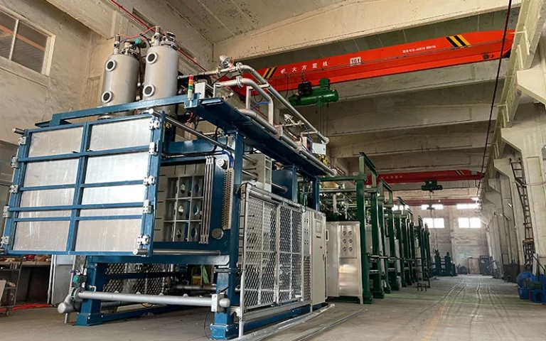
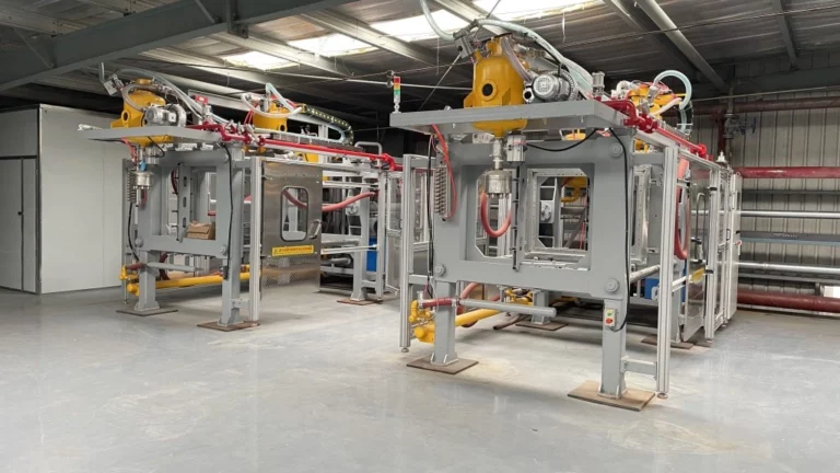
As a professional manufacturer, supplier, and factory specializing in lost foam casting equipment, OC Technology provides advanced intelligent solutions. These solutions support the precise needs of complex lost foam processes for large hollow castings. The company focuses on high-efficiency, energy-saving production lines and integrated systems. These systems improve process stability and casting quality. Manufacturers and foundries that look for reliable lost foam casting equipment can gain from OC Technology’s turnkey solutions. The solutions cover systems for pattern preparation, coating, drying, and vacuum management. Key equipment offerings include central vacuum systems and lift type paint mixers. These items are engineered for optimized lost foam operations. Contact OC Technology to explore customized equipment. This equipment meets demanding production needs and raises overall foundry performance.
FAQ
What is the main challenge in lost foam casting for large hollow castings?
The primary challenge is managing the pressure differential between external and internal sand. This differential arises from insufficient vacuum in the hollow cavity. It increases the risk of mold collapse, swelling, and gas-related defects.
How does internal vacuum management improve lost foam casting of hollow structures?
Internal vacuum ducts supply direct evacuation of pyrolysis gases from the core area. They increase internal vacuum pressure. They strengthen the sand. They also reduce destructive pressure differences that cause instability.
What gating approach works best for tall hollow castings in lost foam casting?
External stepped or staggered side gating preserves internal vacuum integrity. It promotes controlled bottom-up filling. It supports progressive solidification. It also minimizes turbulence.
Why is pattern reinforcement required for large hollow foam patterns?
Large thin-walled patterns do not have enough rigidity. They can deform during handling, coating, and sand compaction. An internal skeleton ensures dimensional stability throughout the entire process.
What typical vacuum levels are applied in lost foam casting for iron hollow parts?
Operational vacuum levels usually range from negative 0.04 to 0.06 megapascals. Precise control remains essential for effective sand compaction and gas removal in hollow sections.