
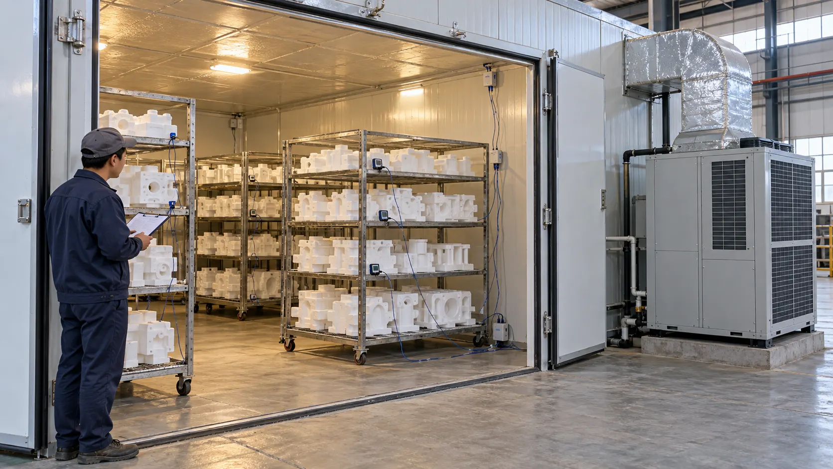
Validate airflow and temperature uniformity in a lost foam drying room with two linked studies: an airflow map and a multipoint temperature map. Run both with a documented room configuration and a representative load. The controller display alone cannot prove uniform conditions around every EPS pattern. A useful test must identify the qualified working zone, capture warm-up and steady operation, challenge likely hot and cold locations, and confirm that the same load reaches the foundry’s defined release condition.
Define the Acceptance Criteria Before Testing
Start with the process requirement, not a generic temperature tolerance. Record the target air-temperature range, permitted variation between measurement points, stabilization rule, recovery time after a door opening, humidity or dehumidification requirement, and the condition that allows a pattern or coated cluster to leave the room. These limits depend on the EPS grade, pattern geometry, coating system, loading method, and the next operation.
Separate control accuracy from spatial uniformity. A control sensor may remain close to its setpoint while corners, upper racks, or positions near the door behave differently. Ouchen’s máy sấy không khí trong nhà page describes intelligent temperature control and customized temperature, humidity, and wind-field solutions. Project acceptance should still verify the complete working zone under the intended duty.
Fix the Test Configuration and Representative Load
Document the supply and return arrangement, fan settings, damper positions, door condition, rack layout, sensor locations, and data-logging interval. Then select a load that represents production. Include the normal rack population and the largest or most airflow-restrictive pattern family. If an empty-room test is used for commissioning, follow it with a loaded test because racks and closely spaced patterns can redirect circulation.
- Record ambient temperature and humidity before each run.
- Use the same loading orientation and spacing planned for production.
- Identify door-side, high, low, corner, center, supply-side, and return-side positions.
- Calibrate or verify test instruments before use and retain their identification.
Map Airflow Before Interpreting Temperature
Use a suitable calibrated air-velocity instrument to measure a defined grid at the supply face, return face, and representative load planes. Record velocity and direction, not only an average. A high average can hide a fast channel beside a stagnant zone. Repeat measurements after the room reaches its normal fan condition and with the production load in place.
Check for short-circuiting from supply to return, weak circulation behind racks, obstruction by large patterns, and strong jets directed at one surface. Where visual confirmation is useful, use a clean, supplier-approved airflow visualization method that will not contaminate EPS or coating. Treat the airflow map as diagnostic evidence; it explains why a temperature location is slow to heat or slow to recover.
Run the Loaded Temperature Mapping Test
Place independent data loggers or thermocouples throughout the qualified working zone. At minimum, cover upper and lower levels, corners, the center, positions close to supply and return air, the door area, and locations shielded by the load. Add sensors on or beside representative patterns when the process needs evidence of what the load experiences rather than room air alone. Do not use a universal sensor count; scale the grid to the room, rack arrangement, and risk.
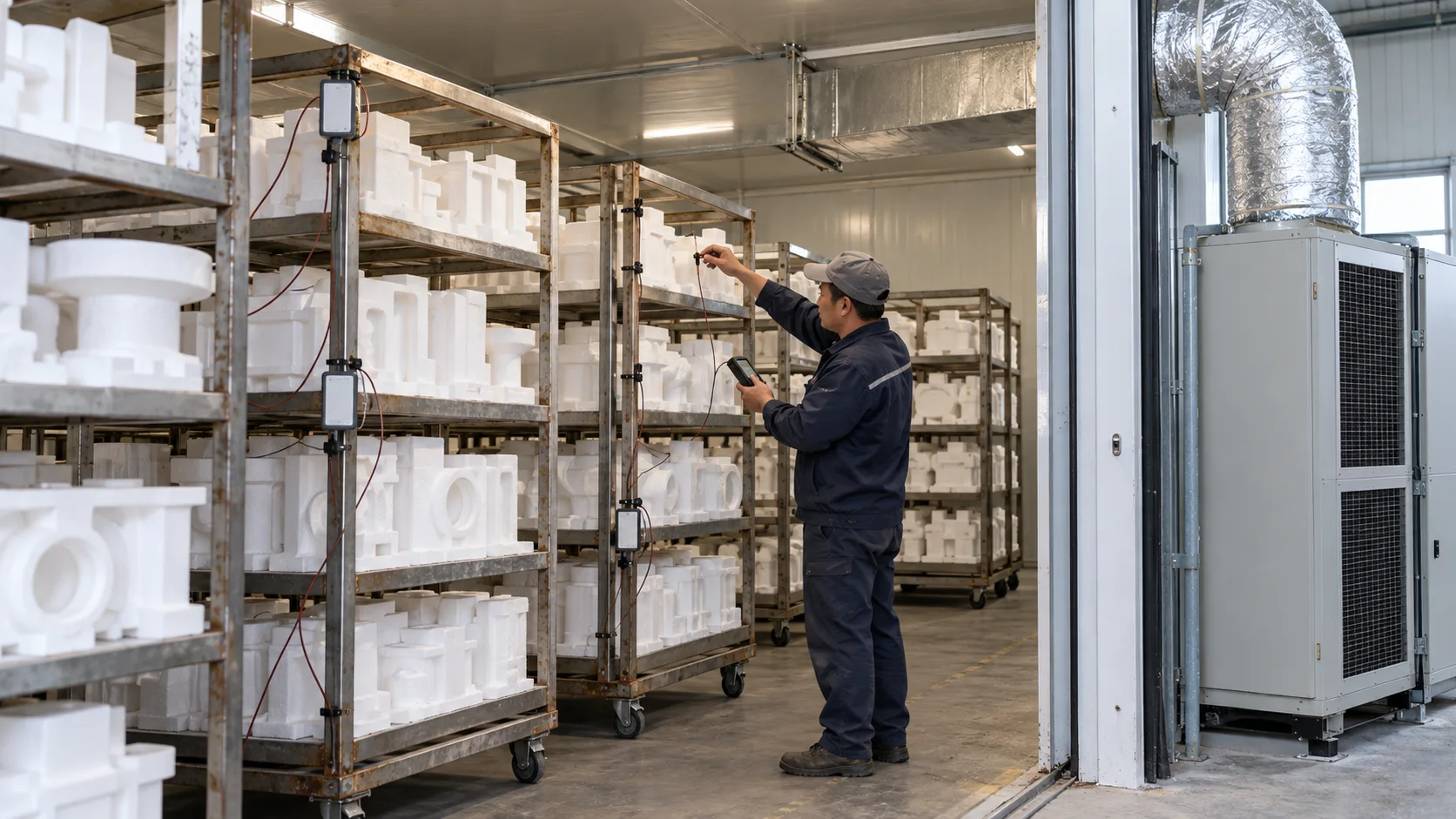
Log the complete cycle: startup, approach to setpoint, stabilization, steady operation, a defined door-opening challenge when relevant, and recovery. Compare every channel over the agreed evaluation period. Report the hottest point, coldest point, point-to-point spread, time to stabilization, and recovery time. One snapshot is insufficient because a location may cycle above and below the limit at different times.
Mount sensors so they do not touch walls, ductwork, racks, or other surfaces unless a surface temperature is intentionally being measured. Protect lead wires from door gaps and direct supply jets. Run a repeat cycle without changing the setup when the first result is close to the limit or contains an unexplained excursion. Agreement between runs strengthens the conclusion; a different pattern suggests an unstable operating condition, a moved sensor, or an intermittent airflow restriction that needs investigation.
Connect Room Conditions to Pattern Release
Uniform air temperature does not by itself prove uniform drying. Record relative humidity or the project’s approved dehumidification indicator, and verify patterns with the agreed release method. Depending on the process, that may be a stable weight trend, a coating or handling condition, or another validated plant test. The related guide to selecting an air source heat pump drying unit explains why the release condition must be defined around the actual pattern and coating system.
Diagnose Nonuniform Results Systematically
| Observed pattern | Likely mechanism to investigate | Useful confirmation |
| Cold corner or lower rack | Weak circulation or obstruction | Compare local velocity with adjacent points |
| Hot supply-side location | Direct jet or poor diffusion | Map direction and inspect diffuser position |
| Slow door-side recovery | Infiltration or insufficient circulation | Repeat a timed door-opening challenge |
| Stable controller but wide room spread | Sensor location does not represent the load | Compare control sensor with the mapping grid |
| Uniform air but uneven release | Load spacing, coating, or moisture-transfer difference | Compare pattern-level data and release checks |
Change one controlled variable at a time. Repositioning a rack, opening a damper, and changing fan speed together may improve the result but will not show which change corrected it. After an adjustment, repeat the same mapped test with the same load and evaluation rule.
Build the Acceptance Record
The final record should include a room drawing, qualified working zone, load photographs, airflow grid, sensor map, instrument IDs, calibration status, setpoints, fan and damper settings, ambient conditions, time-series data, calculations, deviations, corrective actions, and the signed acceptance result. Preserve both the empty and loaded studies when both were performed. Repeat the relevant test after changes that can affect distribution, such as fan replacement, duct or diffuser changes, rack redesign, control-sensor relocation, or a substantial change in loading density.
Use the Findings to Specify Equipment and Layout
A failed map does not automatically mean the heat source is undersized. The cause may be distribution, return-air placement, rack blockage, door leakage, or control-sensor position. Review the result against Ouchen’s air dryer product range and the wider danh mục thiết bị tạo bọt bị mất when a layout or equipment change is being considered. The final arrangement should be confirmed from room dimensions, load plans, utilities, and the required acceptance test.
Phần kết luận
Airflow and temperature uniformity must be demonstrated across the loaded working zone, not inferred from one controller. Define limits, map velocity, log multiple temperatures through the complete operating cycle, connect the result to pattern release, and retest after corrective changes.
Câu hỏi thường gặp
Should the room be tested empty or loaded
An empty-room test provides a commissioning baseline, but a representative loaded test is normally more useful for production acceptance because racks and patterns alter airflow.
How many temperature sensors are required
There is no universal count for every lost foam drying room. Use enough points to cover the qualified volume, levels, corners, center, supply and return areas, door influence, and likely shielded locations.
Does a stable controller prove uniform drying
No. It shows the condition at the control sensor. Spatial mapping and pattern-release checks are needed to verify the whole working zone and the actual load.
When should the mapping study be repeated
Repeat it after distribution-sensitive changes and at the interval defined by the plant’s quality plan. A major load-layout change can justify a new loaded study even when the equipment is unchanged.
For an application review, send Ouchen’s technical team the room drawing, rack and pattern layout, target conditions, load schedule, utility data, existing temperature records, and the proposed acceptance limits.


 Vietnamese
 English
 Arabic
 Hindi
 Indonesian
 Japanese
 Korean
 Malay
 Portuguese
 Spanish
 Thai