
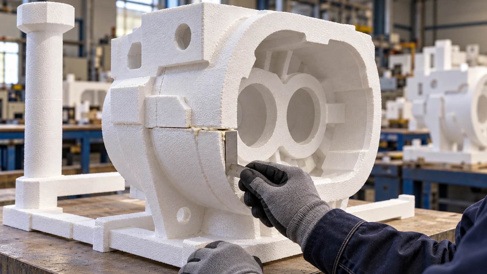
Inspect lost foam pattern joints before coating, because coating can hide the seam. Most EPS foam pattern bonding problems fit four categories: misalignment, open gaps, excessive adhesive, and weak bonding. Each needs a defined visual or dimensional check, a containment action, and process records that connect the joint condition with coating behavior, sand compaction, metal filling, and final casting inspection.
Why Bonding Defects Matter Beyond the White Area
A foam joint becomes part of the evaporative pattern. A step or gap changes geometry and may disturb coating thickness. Excess adhesive adds material that must decompose during pouring. A weak joint may open during handling, coating, drying, or vibration, then appear later as a dimensional change, surface mark, gas-related indication, or interrupted metal flow.
Do not assign a casting defect to bonding from appearance alone. Map the joint and compare it with the casting indication, then review coating, moisture, compaction, gating, pouring, and metal conditions. Ouchen’s overview of common lost foam casting defects provides the broader context; the checks below focus on the bonded pattern.
Misalignment and Steps at the Joint
Misalignment occurs when two pattern sections do not share the intended datum. Common causes include worn or contaminated locators, incorrect fixture loading, uneven clamp force, part warpage, adhesive that skins before the parts seat, and motion while the joint cools. Dimensional variation from molding can also exceed the fixture’s ability to position both halves.
Inspect the seam under consistent lighting and use a gauge, profile template, or noncontact method when tolerance requires it. Measure at specified points. A repeated offset in one direction points to datums or fixture calibration; random offset suggests part variation, debris, loading technique, or unstable clamping.
Open Gaps and Incomplete Contact
Foam pattern joint gaps may result from distortion, insufficient adhesive, poor wetting, blocked dispensing, short hold time, premature release, or uneven fixture support. A gap can also form after bonding when the assembly is lifted from one end or stored without adequate support.
Inspect the full seam, including corners and transitions. Backlighting can reveal open sections on thin patterns, while a defined feeler gauge can confirm an opening where access is safe. Map the location. Repeated failure at one point calls for review of local support, adhesive coverage, and the mating surface.
Excess Adhesive and Squeeze Out
Excess adhesive usually comes from an oversized bead, unstable pressure, excessive melt temperature, slow nozzle shutoff, incorrect path overlap, or excessive clamp force. Thick squeeze-out may interfere with coating and adds a concentrated decomposition load at the joint. Removing the visible bead after bonding does not prove that the adhesive layer inside the joint is controlled.
Measure adhesive output by shot mass, an approved test bead, or part mass change. Keep temperature, pressure, nozzle, and timing records. Research on low-thermal-degradation hot-melt adhesives documents how a hot-melt joint can slow the metal front when the adhesive decomposes more slowly than EPS. Control both adhesive selection and applied quantity.
Weak Bonds and Joint Separation
A joint can look acceptable and still lack strength. Causes include low adhesive temperature, poor wetting, contamination, expired or incorrect material, excessive open time, insufficient contact pressure, short hold time, or movement before the adhesive sets. Foam damaged by heat or solvent may also lose strength next to the bond line.
Use a documented handling or proof-load check that represents the next process step without damaging conforming patterns. This may involve approved lifting points or a controlled force on a witness sample. The production check must detect drift soon enough to contain affected assemblies.
Inspection Plan Before Coating
Place the inspection where the seam is still visible and the joint has reached the specified cooling or curing condition. The plan should define the method, sampling frequency, acceptance limit, and reaction for each characteristic.
| Checkpoint | Inspection method | Reaction when out of limit |
| Alignment | Measure offset at named datum points | Hold the part and verify fixture loading and calibration |
| Gap | Visual seam check plus gauge where accessible | Map the location and inspect support and adhesive coverage |
| Adhesive amount | Shot mass or approved bead check | Stop and verify temperature pressure nozzle and recipe |
| Bond integrity | Defined handling or witness-sample test | Quarantine the interval since the last accepted check |
| Pattern shape | Template or dimensional check after cooling | Review clamp force heat input and removal method |
Photographs should include a scale and pattern ID. Use the same defect names across production, quality, and casting inspection. A seam that can be filled or trimmed may still need engineering approval because rework changes material or geometry.
Prevent Defects With Controlled Standard Work
A stable process starts with clean mating surfaces, verified fixture condition, the correct adhesive and recipe, and parts within their molding limits. Define the sequence from loading through removal. Include adhesive warm-up, temperature verification, nozzle check, maximum open time, clamp or hold time, cooling time, and the approved handling points.
Require first-piece approval after a fixture or recipe change, new adhesive lot, maintenance, or an extended stop. Trend offset, gap, adhesive output, and bond-check results. Gradual movement can reveal locator wear, heater drift, pump variation, or nozzle buildup.
Trace the Joint Through Coating and Casting
Preserve a joint map with the production record. During coating, note bridging, cracks, or unusual thickness near the seam. Record movement after drying or compaction. Compare the casting with the mapped joint; repeated location correlation is stronger evidence than one matching indication.
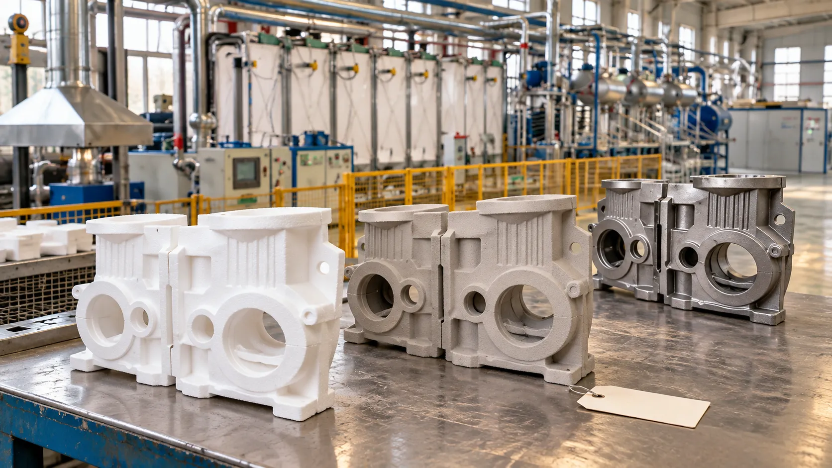
The bonding operation should be reviewed with the equipment used across the lost foam process, because upstream pattern quality and downstream coating, drying, and compaction influence what happens at the seam. Hangzhou Ouchen Technology can discuss these interfaces as part of a line review without assuming that every casting indication originates at the glue joint.
Use Automation Where It Removes a Proven Source of Variation
Automatic adhesive application and fixturing can improve repeatability when manual bead placement, alignment, or hold time is the verified cause. Automation does not correct warped pattern halves, the wrong adhesive, an unstable incoming process, or unclear acceptance criteria. Define the defect mechanism first, then specify the control the equipment must provide.
For a new or upgraded cell, trial the smallest, largest, and most difficult patterns. Verify alignment, adhesive output, heat effect, cycle time, changeover, fault recovery, cleaning, and traceability. The public lost foam equipment portfolio shows adjacent categories that may interface with bonding.
Build an Evidence Package for Root Cause Review
When defects recur, collect pattern ID, joint number, date and time, operator or cell, foam material and density range, adhesive name and lot, temperature, pressure or output setting, open time, hold time, fixture ID, inspection measurements, and photographs. Add coating, drying, compaction, pouring, and casting inspection records when the issue appears downstream.
Use the evidence to test a specific cause. Compare a recurring gap with local support and adhesive coverage, or a casting fold with the mapped joint and adhesive lot. Change one controlled variable at a time. Segregate affected material until the inspection boundary is defined.
Kesimpulan
Control bonding defects before coating. Classify the seam as misaligned, open, over-applied, or weak; measure it at defined points; and preserve the joint location through later operations. Prevention requires stable parts, clean fixtures, controlled adhesive output, adequate hold time, and a reaction plan for the affected interval.
Pertanyaan yang Sering Ditanyakan
Can a visible glue bead be accepted
Only if the approved process and drawing allow it. A visible bead does not reveal the adhesive thickness inside the joint, so application output and joint geometry still need defined limits.
Should every casting defect near a seam be blamed on bonding
No. Use the joint map and review coating, moisture, compaction, gating, pouring, and metal conditions. Repeated location correlation and process evidence are needed before assigning root cause.
When should the joint be inspected
Inspect after the specified cooling or curing time and before coating hides the seam. Add checks after handling or compaction when those steps can move or load the assembly.
What data should accompany a defect sample
Include pattern and joint identification, measured offset or gap, photographs with scale, adhesive and foam details, process settings, timing, fixture ID, and relevant downstream records.
For a focused review, send Ouchen’s technical team the evidence: joint photos, drawings, adhesive details, inspection limits, production rate, and linked casting results.


 Indonesian
 English
 Arabic
 Hindi
 Japanese
 Korean
 Malay
 Portuguese
 Spanish
 Thai
 Vietnamese